Without the use of the automated centerline extraction algorithm, the original hallway centerline files and junction (node) files were created manually in ArcGIS.
Assuming that we are using a georeferenced polygon shapefile or PostGIS table of the building’s rooms, stairways, and elevators we can begin the manual process of digitizing the centerlines. These centerline files are analogous to routes humans (in this case during emergencies), use to traverse the building and get from point A to point B.
In the case of Woodward Hall, I had already preprocessed the shapefiles containing the building geometry. Using the identified hallways in this building, I manually digitized these routes as line feature types in ArcGIS. This was achieved by a combination of “snapping” to the center of the polygon and manually drawing straight line segments to common junction points (i.e. the end of two hallways). After this step is completed, I have a file representing lines to all possible routes in the building, including access to rooms and other important features.
Using a tool called “network analyst” I was able to convert this line feature type into what is called a network shapefile, which creates junctions at the end of each edge in the graph. These junction points would be used to store attribute information on their specific function in the graph. For example, if a line segment ended by a main entrance, it would be specifically labeled to indicate this in the attributes of said line junction file. Or if the junction happened to fall on a stairway, as is the case in the screenshot below, we would label it as such. This continues until all rooms, elevators, stairways, and general hallway junctions are accounted for with a unique identifying label.
Line and Junction file for a sample floor. Hallway polygons are blue, rooms green, and stairways purple.
Identifying Junctions and Room #'s based on CAD file documentation and existing Polygon attributes.
Once everything is labeled properly, the files are uploaded into the PostGIS database. Before we developed our automation methods, our graph model used the tables representing the graph to programmatically construct a 3D graph in order to achieve route finding and other functions.
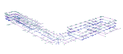
This is the result of the 3D Woodward hall graph running in our Visualization Program.
This is the graph running in ArcGIS, which did not support the 3D functionality required for multiple floors.
Another process that was completed manually, and in the future will also be automated, is the creation of hallway “segments” that we used for blocking sections of the building. These were created from the same polygon files from which centerlines were extracted from, and were representative of the area the entire hallway space covered. We divided these into sections that were delineated manually in ArcGIS and were intended to be representative of sections of the hallways for the purposes of creating something the user could easily click on to indicate an impediment in that section of the building.
Each different hallway color represents a different segment the user can select to block in the graph
This manual process of digitizing the hallway centerlines usually takes on average about 1 hour to actually create the centerline file, and another 1 or 2 hours to label the junction file after being converted into a network. If the following floors in the building are assumed to be of the same structure and composition, then these files can simply be copied to their equal on the second or remaining floors. Since this is rarely the case, (and in fact was not the case in both building files we presented as examples) each floor has to go through this manual process in order to generate the geometry required for graph construction.
Obviously, for large buildings of high-complexity these steps can take several full work-days (16-20 hours) to complete. Especially when you’re dealing with several buildings in an urban cluster environment, manual creation of the 3D graph model is not viable, and strengthens the argument for automation of these processes.


